Secret Location: Arcade Cabinet
As happens so often in my career, I got an email asking “We want *insert object here*. Is that something you can do?“
In this situation it was the amazing Ryan Andal of Secret Location and the “object” was a rolling arcade cabinet. Something that could connect to a service over Wi-Fi. I asked a few questions to gauge exactly what the ask was but it took very little time for me to say “Yes!”
Once they passed over the briefing doc, along with any supporting visual, I was able to get down to it. There were 3 stages; prototype, testing & design, and production.
Prototype
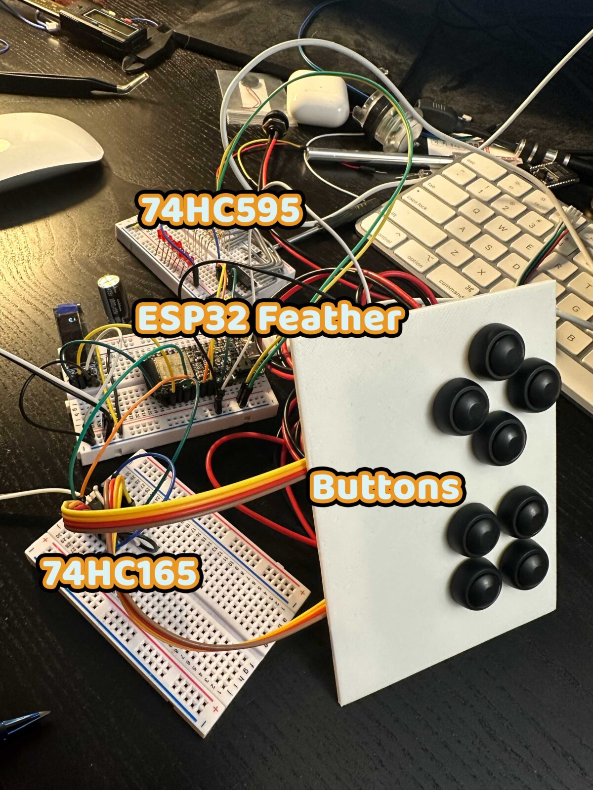
While we figured out what would be best for communication, I worked on developing a prototype that could fulfill two key points. Be portable. Be easy to use. I did what I usually do and started a breadboard version of the setup. Most old-school arcade systems use shift registers as inputs as they’re very stable and send byte information (small in this case 8 bits). So that means it would compact and fast. My initial set up had a second shift register to show me the values.
It might look weird but one set of four buttons is a joystick. Old school 4-way joysticks are essentially a stick pushing buttons.

Those red and black “doohickeys” with the tabs on the bottom? Yup. Switches. You can see them more clearly here.

Like any digital switch, once connected, they send a HIGH or LOW signal. ON or OFF. And since this is the same as the arcade buttons, I could connect all 8 to a single shift register (74HC595) and retrieve a byte value for each. Think of it like this; 0x00000000 is 0xUDLTABXY (or however the buttons are hooked up. Meaning if I was pushing the A button and pushing up on the joystick, my byte would like 0x10001000. And when I say this is fast, hoobaby!
Now that’s one part of the system solved. I knew I’d be working with an ESP32 board because of the need for Wi-Fi. I have been using some kind of ESP32 for my projects since discovering the chipset a couple of years ago. The right board will have Wi-Fi and bluetooth and a lot of inputs. I used it on my Molson cans and the Corona fridge. Back to the portable prototype. I hopped into Fusion and made a basic box with top-loaded components, room for the controller and a battery.
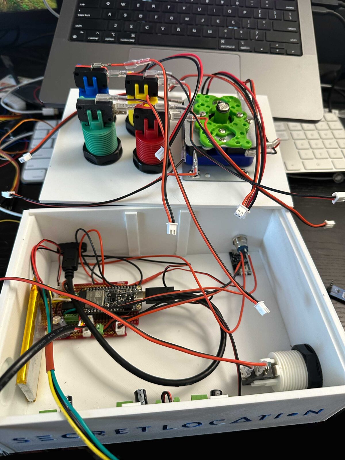
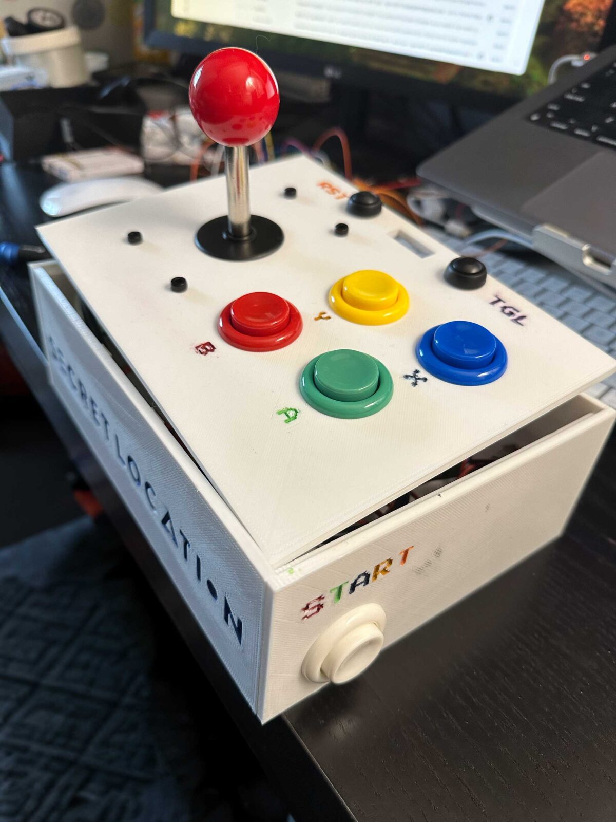
I added some indented lettering and let one of my kids paint it. Might have been me doing a mediocre paint job, but I’ll never admit it. This prototype allowed them to communicate with their services using OSC (with the MicroOSC library). I sent a byte through to their receiver over Wi-Fi.
Once the prototype was worked out, I could turn my attention to the testing.
Testing & Design
There were a few additional considerations to the controller. The cabinet is mobile while being safe. The controls are as a user-friendly as possible. Recognizable in form and function. A later addition was to design to be flat pack for storage.
First up was cabinet design. My initial stab at this was a more complex design that would require some advanced cabinetry techniques. Like kerf cuts. Scoring the plywood to the last layer to allow bends. Note this design was before the flat pack request.
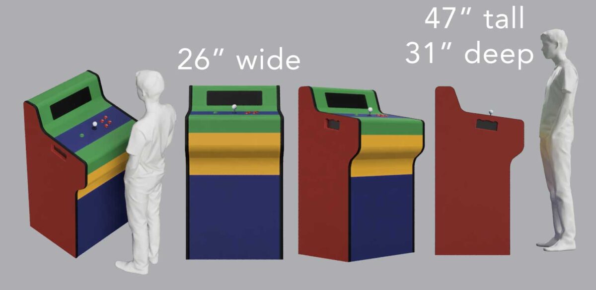
I was doing my best to make this look like a classic arcade cabinet. The feedback was that it was too big. But you can see I was making some technical decisions.
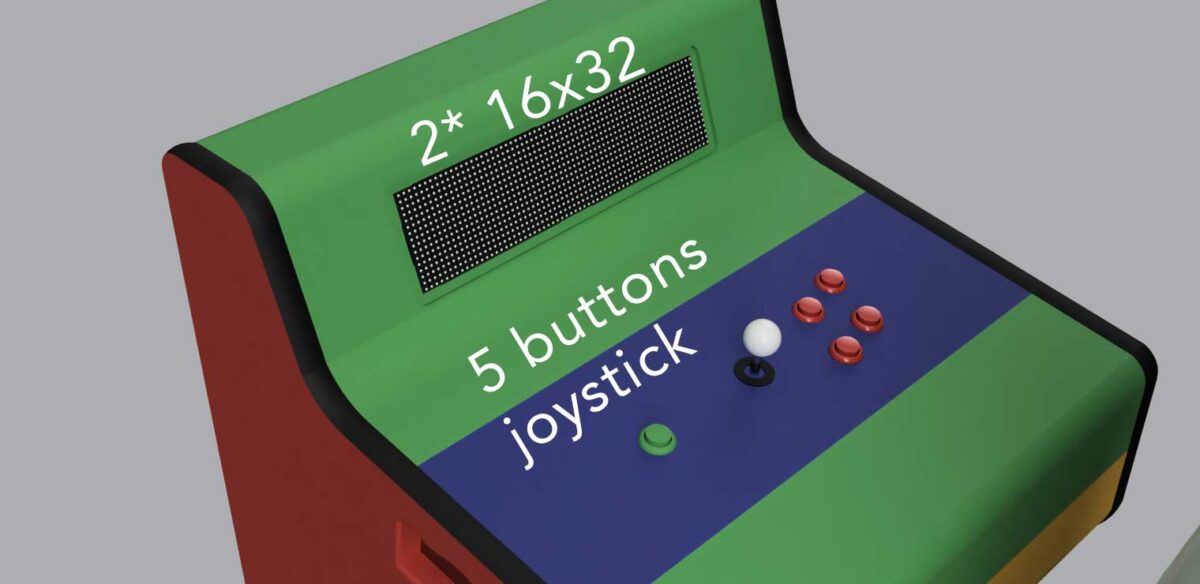
I added an RGB LED matrix for a pixel based scoreboard. The components of the cabinet were broken down into colors so I could illustrate how it would be assembled.
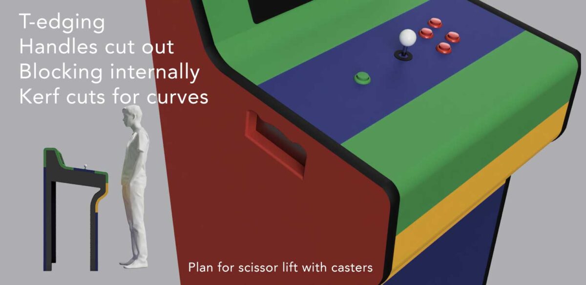
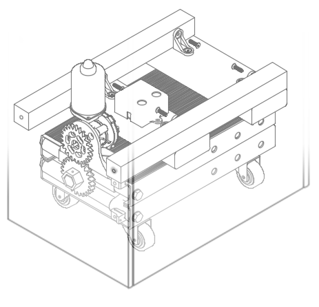
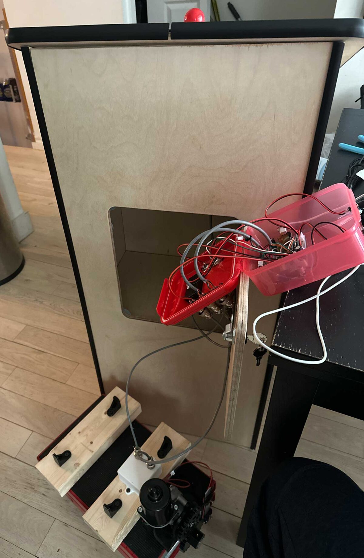
T-molding was planned for that classic arcade cabinet look. Handles were cut out to allow for the mobility aspect. And you can see a note for a scissor lift. Let’s talk about the scissor lift. I initially was under the impression, the need for mobility was that the user would be moving about the space. Therefore the cabinet would have to be raised and lowered. So I began the search for a good solution. I ended up with a combination of a motorcycle lift with added casters and a windshield wiper motor along with gearing to raise and lower the lift.

Motorcycle lift

Windshield wiper motor
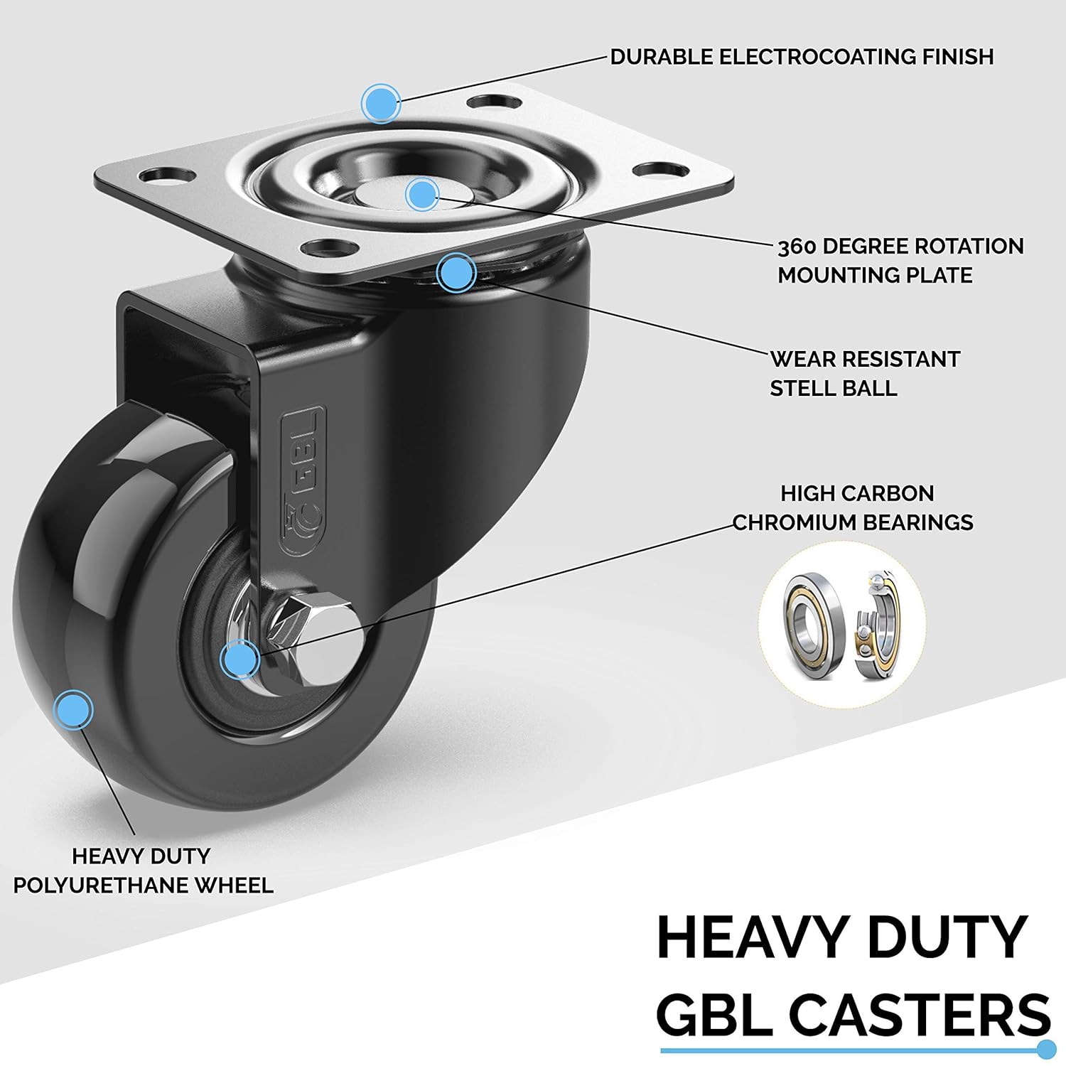
Casters
I popped into fusion and modelled all of these elements to figure out mounting of the motor, placing the casters, gearing with proper meshing. After a number of attempts, I managed to get it all to work.
I used a L298N driver motor. The windshield wiper motor is used in a lot of droid building as it has high torque capability so it seemed a natural choice for the motorcycle lift. The lift felt like a good solution due to its ability to lift up to 1,100 LBS (500 KG). Also, it’s heavy. 30 LBS (13.2 KG). Since it is sitting in the base of the cabinet it provides excellent counterweight against toppling. See the need for “mobile while being safe”.
As you can see, I added blocking to attach to and drilled directly to the to the lift to affix everything. The gears had heat set inserts and set screws, the 3D printed motor mount had screw holes and mounted onto the lift. The entire assembly was mounted into the cabinet.
Production
Speaking of the cabinet, after some back and forth with the team, we netted out with a much simpler design. Thanks to the previously-mentioned ask of a flat pack for storage, I made the design of the cabinet simpler. But also it looked so good.
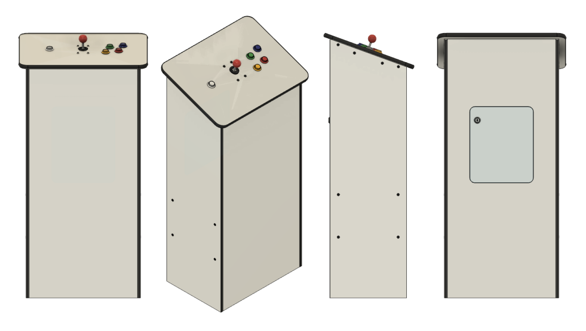
Cabinet final design
I married the use of CNC cut materials, 3/4″ plywood, 1/2″ plywood, 2×2 dimensional lumber and 6mm (1/4″ cast clear acrylic). I was so grateful to Tim Willison of the Toronto Tool Library Makerspace in helping me out with the cutting.
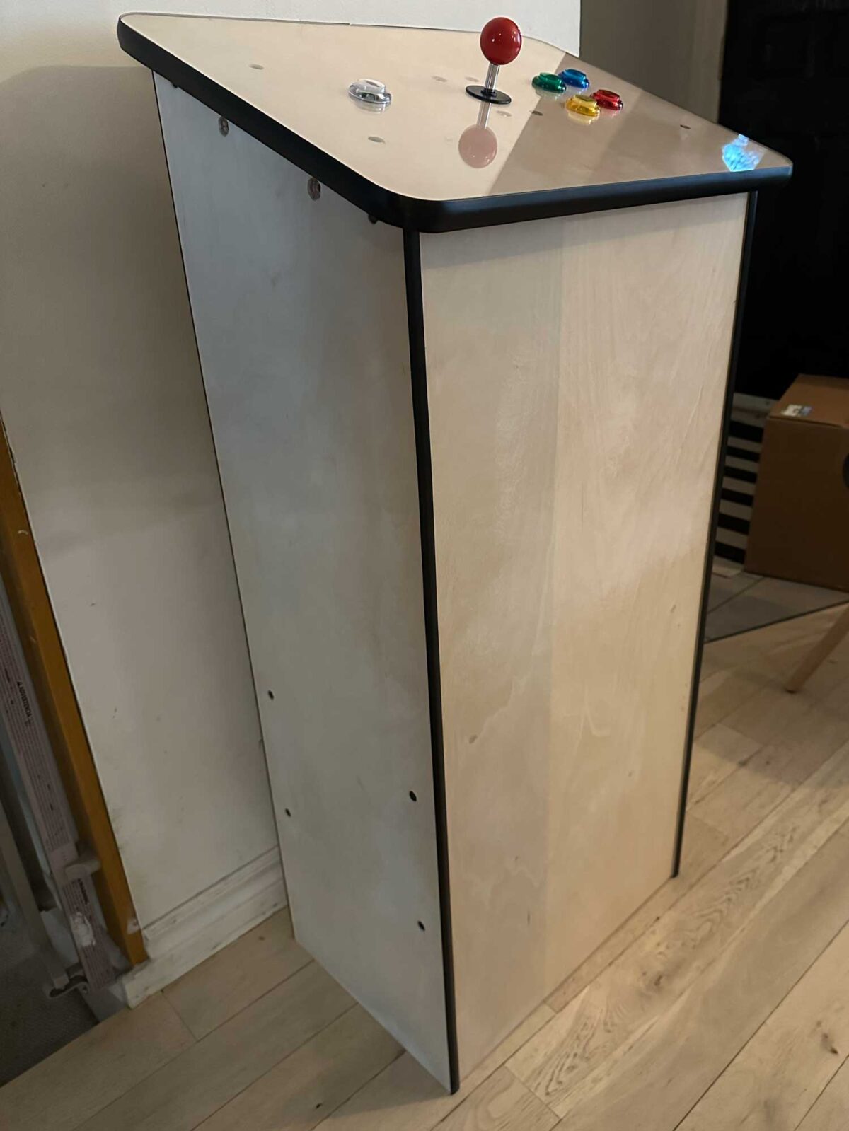
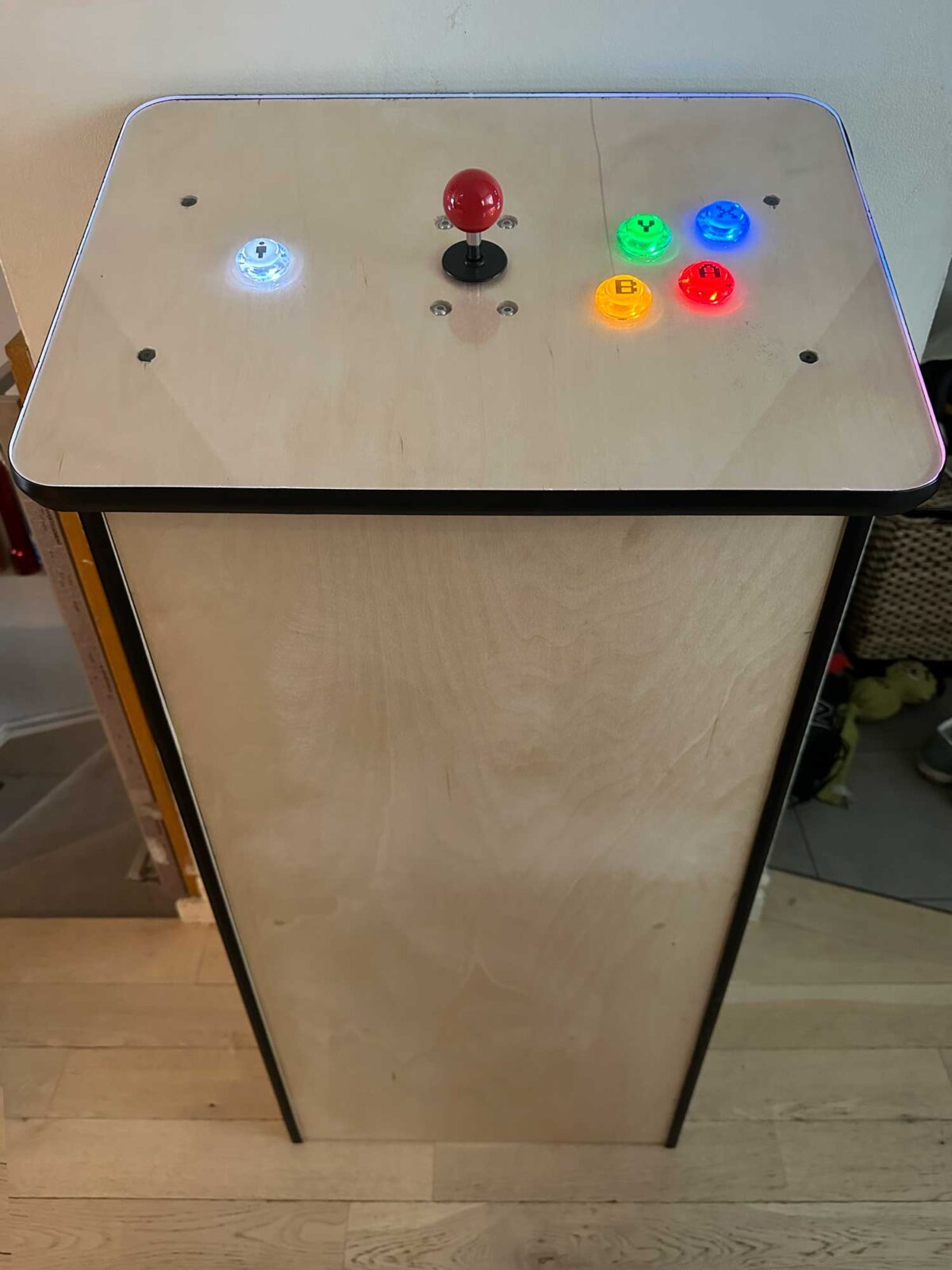
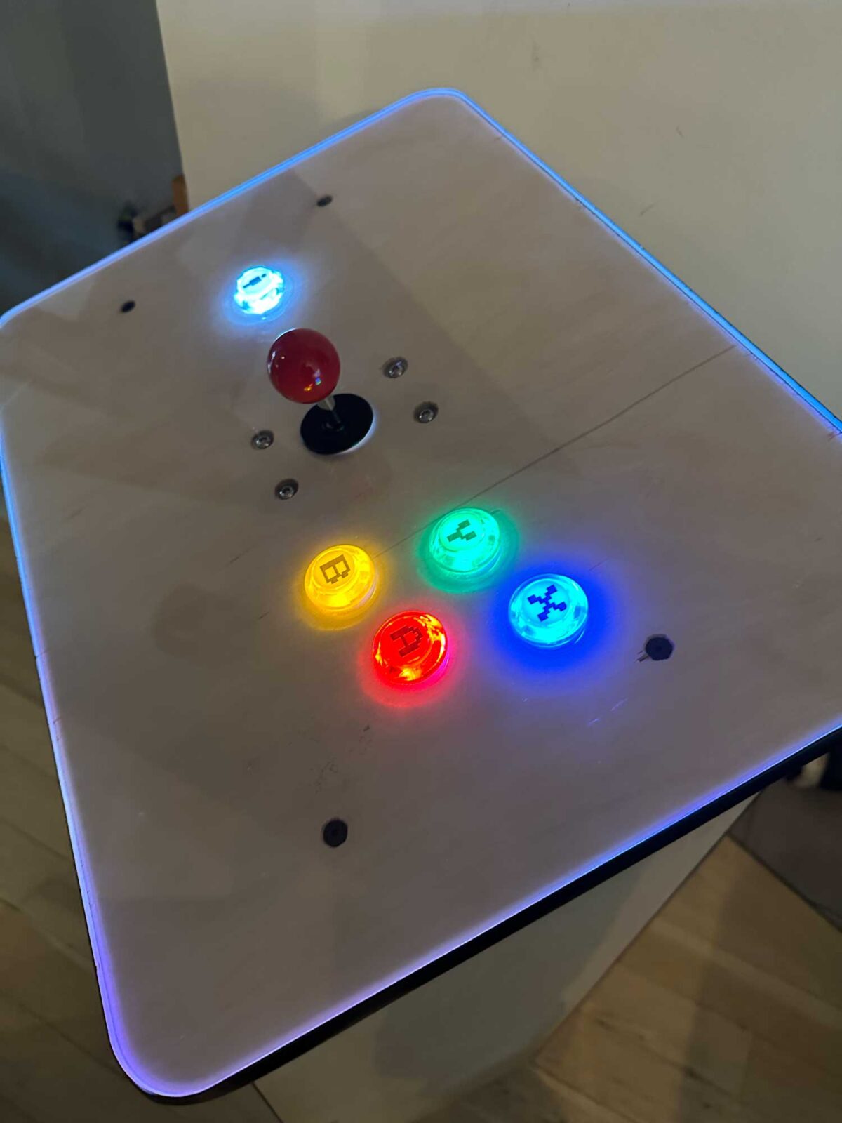
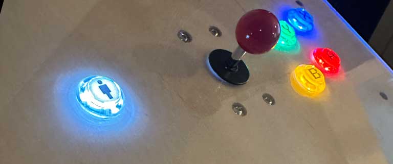
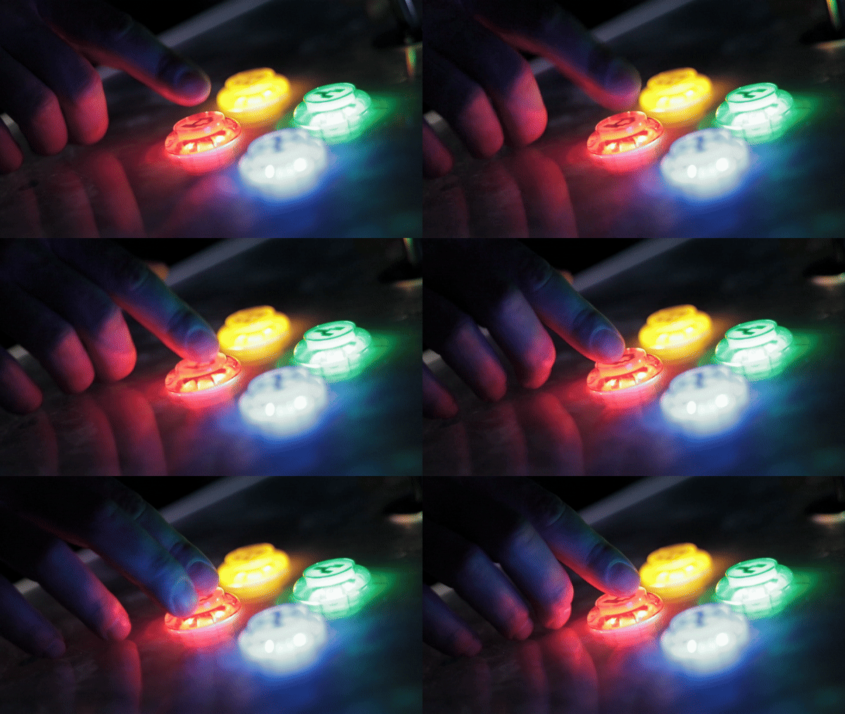
The top in the last picture has what looks like exposed screws. However, these are covered by the acrylic “keep it safe”. The only elements on the top that can interacted with are the buttons and joystick. The 3/4″ T-molding prevents the edge of the acrylic to be interfered with as well. There was a bonus effect of the cut edges creating an edge-lit situation with the LED buttons. The end concept would be to lift off the acrylic, buttons and joystick, apply vinyl to the plywood top and put everything back on.
So what I delivered was a raw cabinet that could be easily wrapped for any purpose, the entire structure goes together with 16 screws.

The top is an assembly connected to the controller with three airline connectors. Thank you to Hoss Gifford for the suggestion of this type of connector. They’re great for a secure connection.
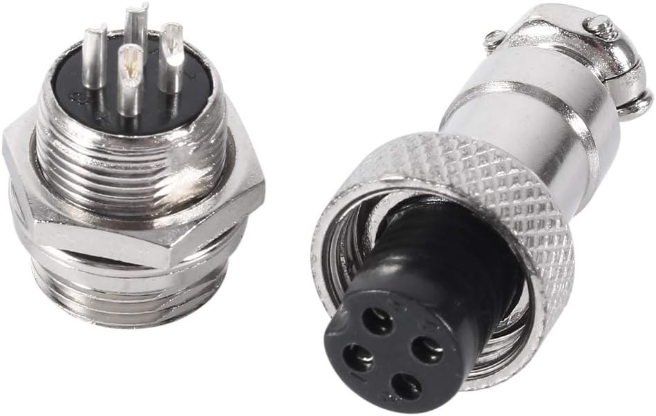
The Manual
Probably the most fun part at the end was creating the assembly manual. I will make operations manual for client for every device/object I create. In this case, I wanted to make the assembly manual as easy to follow as possible. I decide to emulate the gold standard of flat pack assembly manuals by designing a fake IKEA manual.
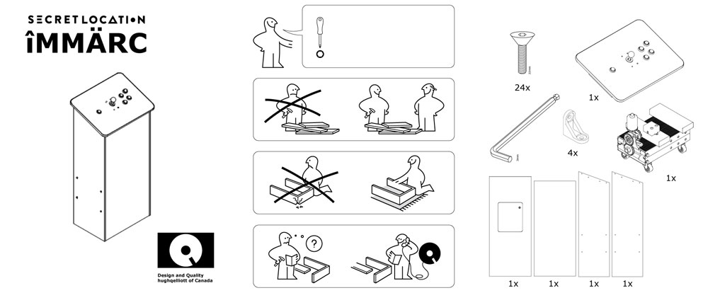


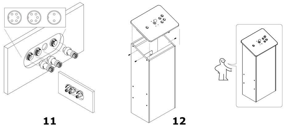
In designing this I learned the advantage of modelling my components in Fusion. They can added as drawings and they export as a line drawing. Perfect for an IKEA style manual. I am particularly proud of this as is it simultaneously useful AND funny.
